Reverse Engineering Firmware (in Mice)
Decrypting the Optical Sensor Firmware
After having analyzed the USB controller’s firmware in the previous post, there was still a region left unanalyzed. That region has high entropy and it turns out that this region is actually two repetitions of the same 3070-byte blob. Looking at references to the start of either blob, only the second is referenced by the firmware.
That sensor is an ADNS-9800 (I saw that when opening the mouse), and it even has a datasheet, what a luxury! However it does not say anything about the contents of the firmware itself, only that it can be 1.5kB or 3kB (in this case the latter).
What is that blob?
Knowing the model does allow searching for other firmware revisions. After inspecting the internet, aside from the one on the mouse I found 6 other revisions, called A0, A4, A4b, A5, A6 and AA (the mouse itself has AB). They all are mostly dissimilar when comparing them byte-by-byte, only A4 and A4b have some common longer byte sequences. Most common bytes - outside of the A4-A4b pair - are near the start of the respective pair.
Every image has high entropy. That usually means either compression or encryption. However, compression does not really fit here: the files all have the exact same size, are very different and have no obvious padding.
So it’s probably encryption. On a small device like an optical sensor, it can’t be very complex so let’s try our hands at cracking it.
Asymmetric crypto is unlikely here, so let’s focus on symmetric one. The are generally two categories of symmetric ciphers, block ciphers and stream ciphers. Normally, stream ciphers require less processing power and memory, so let’s try that first since it is more likely.
In a stream cipher, one has a key stream generated by a given key that should look as random as possible, and XORs (⊕) that with the message. If K is the keystream and M the message, E = K ⊕ M is the encrypted message. One can then decrypt it by again XORing with the keystream, because K ⊕ E = K ⊕ (K ⊕ M) = (K ⊕ K) ⊕ M = M.
Because there is more than one file, they can have different keys and therefore different keystreams. If we XOR two of them together, we get E1 ⊕ E2 = K1 ⊕ K 2 ⊕ M1 ⊕ M2.
But our files are hopefully revisions of the same firmware, so there’s a great chance parts of the messages will be the same. In this case, M1 ⊕ M2 = 0 and therefore E1 ⊕ E2 = K1 ⊕ K2. This allows us to look for possible regularities in the keystream without the message interfering, with the caveat that it is XORed with another keystream.
Comparing the different revisions
Take a look at this diagram of the byte values from the XOR between revisions AA and AB.
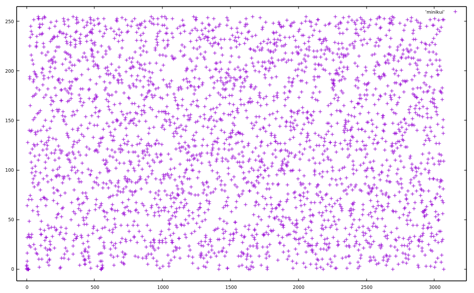
Looks pretty random. But at the beginning there’s some concentration of points, let’s zoom into that.
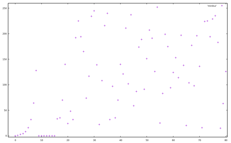
Huh, so at the beginning it looks rather exponential. The values themselves seem to double, a pattern which breaks down a bit later. After byte 8 it jumps to 0, and was 128 before that, so that could still be considered doubling.
But it still doubles in some places after the first 15 bytes: The bytes 17-19 double, same with 20-21 and it does so at many more places throughout the file.
Instead of showing the values of the individual bytes, we could show the amount the next byte deviates from the previous one.
One could use subtraction, but in the case of bitwise operations, XOR makes more sense.
If x[i] is the ith byte of the previous file (the XOR of AA and AB), we simply calculate y[i] = x[i] ⊕ (x[i-1]<<1) for each value (which I will call XORed deviation hereafter because I’m bad at naming).
This is the result:
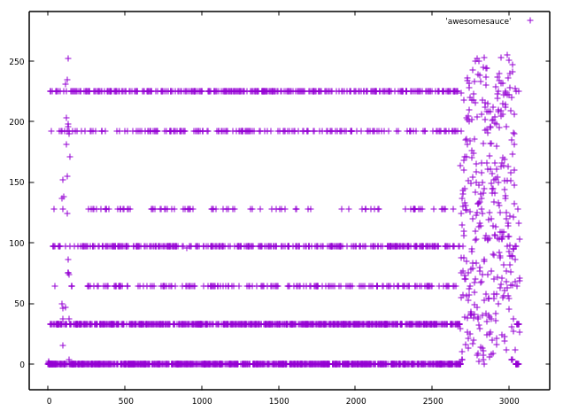
Looks less random than the previous diagram, doesn’t it? These are the counts of the most common (by a wide margin) values
| Value | Number of Occurrence |
|---|---|
| 0x80 | 86 |
| 0x40 | 173 |
| 0xc0 | 174 |
| 0x61 | 327 |
| 0xe1 | 329 |
| 0x21 | 675 |
| 0x00 | 923 |
One then has to consider that this is not the result of a single keystream, but of a XORed version of two keystreams. Indeed, 0x80 = 0x61 ⊕ 0xe1, 0x40 = 0x61 ⊕ 0x21 and 0xc0 = 0xe1 ⊕ 0x21.
If the original keystream contained the values 0x00, 0x21, 0x61 and 0xe1 with respective frequencies 1/2, 1/4, 1/8 and 1/8, this is roughly the distribution that would follow from an XORed stream.
So we have 4 possibilities for a byte of the keystream if we know the previous byte.
That’s not a lot but we do not yet know what the plaintext is supposed to contain, so looking for the right
plaintext would be hard.
There are 7 different firmware files from which we can infer possible values of the keystream. This is done by XORing a pair of files and looking for long sequences just consisting of the those 7 XORed deviations.
If for instance, a particular byte in AA ⊕ AB has the XORed deviation of 0x40 from the previous byte, we know that both AA and AB can either have a XORed deviation of 0x61 or 0x21 at that location.
If we do the same with A6 ⊕ AB and get 0xc0 at the same location, A6 and AB have to be either 0xe1 or 0x61.
But since we already know that AB is 0x61 or 0x21 at that location, the XORed deviation must be 0x61 for AB.
This also lets us infer the values for A6 and AA at that location.
There’s one special pair though: A4 and A4b. These appear to have the exact same keystream, since aforementioned values pop up nowhere and instead abnormally many 0s (not as a XORed deviation, but in the values themselves) show up. This probably means the keystream is derived from the first two bytes of the file, since they’re the same only for this pair. One thing this allows is applying the constraints from the keystream of either A4 or A4b to both at the same time, allowing us to derive more of the keystream.
Getting some plaintext
But with that, we only know the XOR of one byte of the keystream to the shifted version of the previous one. However, after eight bytes of knowing the exact XORed deviations, the unknown part gets completely shifted out and we know the exact values of the keystream, up to a constant XORed value.
Writing a program that does automatically solves the constraints on longer sequences of the 7 XORed deviations, one already obtains 1070 plaintext bytes in A4 and A4b combined without any manual decoding.
Towards the end of this decoded version, one will find many repetitions of the bytes 0x7E.
This is likely padding and is often 0, meaning the constant XOR value is probably 0x7E.
It didn’t pop up yet because we only looked at the relative XOR to the previous value.
In figuring out the type of plaintext, we once again look at the distribution of the bytes:
     33 f5
     36 e5
     38 80
     38 81
     41 dc
     45 f0
     46 75
     47 e0
     54 90
   5004 00
(left is number of occurrences, right is byte value, 00 is also used for indeterminate)
Looks very 8051esque, doesn’t it?
Indeed, looking at the bytes themselves, they do look like 8051 code.
The 80 and 81 pop up because it the firmware seems to store values in XRAM around 0x8000.
Knowing that the plaintext will be 8051 firmware, one can then make an application where one can set the values of the keystream and see the corresponding 8051 disassembly for the plaintext of A4 and A4b. With 2 plaintexts at once, one can then mostly find out which keystream to choose.
Here’s an example of that program:
For some orientation, the first column is the automatically inferred bitmask of possible XORed deviations. The second one is the user-defined override, then two columns of ciphertext (A4, A4b). The 3-wide column after that shows the number of possibilities the keystream can have at that place (in hexadecimal). After that, two pairs of hypothetical plaintext, including disassembly.
I love repetitive work, so I decrypted the whole file within a night, without realizing the time that had gone by. After that, it would be possible to reverse engineer the firmware itself to modify it and then find out the decryption algorithm. However, I kind of wanted to see if one could reverse engineer the cipher from the files themselves (or at least a cipher which happens to decrypt all existing revisions).
I wrote that down here for completeness’ sake, but of course you can skip straight to Dumping the Original Firmware.
Figuring out how the cipher works
Next is to find out how the XORed deviations are chosen. Stream ciphers are often based on LFSRs (linear feedback shift registers) made non-linear by some function. With an LFSR, one basically has n bits that get shifted left and a new bit created by XORing a fixed set of the other bits together. Since I’m bad at explaining, it might be easier to understand by reading the Wikipedia article.
Indeed, the way this keystream is formed kind of looks kind of like a Galois LFSR, which works by XORing the n bits with a constant value if the shifted-out bit is one. However, in this case, it is not a constant value, which makes it non-linear (but still comically weak because of the use of the whole lower byte, instead of one bit, per state). Still, the way the value to XOR is chosen could be part of the n bits in the stream.
First off, the distribution of the XORed deviations has 1/2 0x00, which could mean that we have one bit which decides whether we XOR a value at all.
Then we look at the distribution of the XORed values if they’re not 0.
This is 1/2 0x21, 1/4 0x61 and 1/4 0xe1, which means this can be represented by 2 bits, where two values map to 0x21.
It could be the case that 0x21 actually includes two different values, but they’re different above the 7th bit.
If those two bits are right behind each other, we should see that some transitions don’t happen.
For instance, if 0x61 is triggered by the bit sequence 01 and 0x21 by the bit sequence 00 and the bit sequence gets shifted one left, one could not see 0x21 right behind 0x61.
That’s because the bit sequence is 01 first, and after the shift it is 1?, which can not be 00.
With our decrypted keystream, we can make statistics about that with no problem:
| from\to | 00 |
21 |
61 |
E1 |
|---|---|---|---|---|
00 |
753 | 395 | 213 | 188 |
21 |
399 | 180 | 0 | 189 |
61 |
192 | 94 | 83 | 0 |
E1 |
205 | 99 | 73 | 0 |
It’s a transition table showing the changes of one XORed deviation to the next. The row indicates from, the column indicates to.
The transitions from 0 and to 0 are pretty much the distribution of the values themselves, so one XORed deviation being zero is independent from the specific value it was before.
Interesting are the transitions between the non-zero values. There are forbidden transitions:
0x21doesn’t transition to0x610x61doesn’t transition to0xE10xE1doesn’t transition to itself
If 0xE1 doesn’t transition to itself, it has to be either 01 or 10 as a bit sequence.
Without loss of generality, let it be 10.
For 0x61, because it doesn’t transition to 0xE1, the last bit can’t be 1
But because is able to transition to itself, it has to be the same bit twice, so 00.
Left over are 11 and 01, which must both express as 0x21.
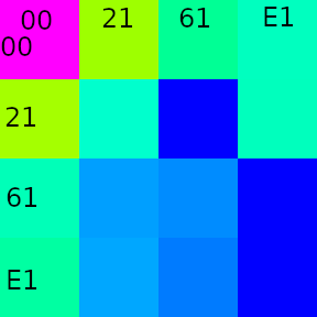
Indeed, one can see how this distribution follows by looking at the de Bruijn graph and contracting the vertices belonging to 0x21 (01 and 11):
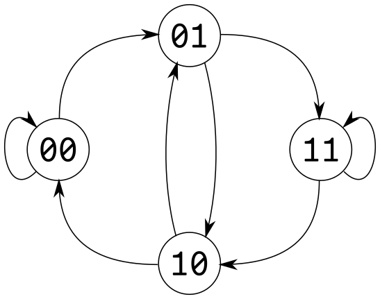
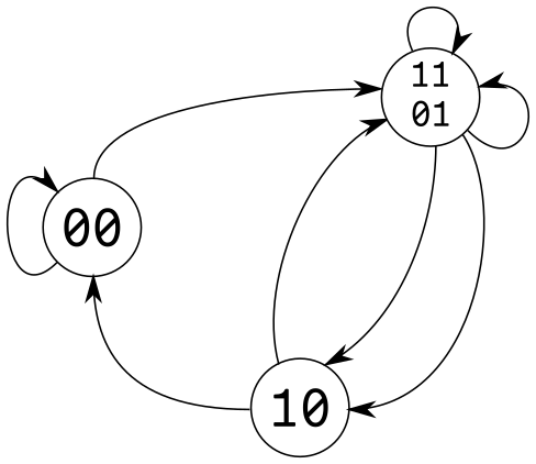
This also explains why some transitions are double the normal value, since 01 and 11 can both map to them (see the double arrows).
So now that we have properly mapped them to bits, we can partially reconstruct a bitstream with one bit per byte of the keystream (called the value bitstream). We can also reconstruct another independent bitstream determined by the XORed deviation being non-zero or not (called the enable bitstream, I hate naming things).
To illustrate them, here’s a part of the keystream with XORed deviation and both bitstreams:
Keystream (^ 0x7E) |
XORed deviation | enable bitstream | value bitstream |
|---|---|---|---|
0x68 |
0x00 |
0 |
(?)0 |
0xD0 |
0x61 |
1 |
(0)1 |
0xC1 |
0x21 |
1 |
(1)1 |
0xA3 |
0x21 |
1 |
(1)1 |
0x67 |
0x21 |
1 |
(1)? |
0xEF |
0x00 |
0 |
(?)? |
0xDE |
0x00 |
0 |
(?)0 |
0xBC |
0xE1 |
1 |
(0)1 |
0x99 |
0x00 |
0 |
(1)? |
0x32 |
0x00 |
0 |
(?)? |
Using the complete image to generate the bitstreams and comparing them, one sees that when shifting the value bitstream left by 5 and comparing it to the enable bitstream, we get many equal bits. This could mean that the bits for determining the value are 5 left to the bit which determines whether the value is XORed. But they are far from exactly equal, which could mean that bits in between are also XORed depending on these bits.
Determining these bits should be no problem with a little linear algebra in GF(2): For each of the four value bitstream bit pairs, one makes 5 variables for the five possible positions in the bitstream that could be XORed when the value is active (5 positions because it’s shifted by 5). Additionally, one can add one more variable in case the value bitstream is actually inverted from what we assume is the bitstream.
Unfortunately, an off-by-one error hindered the program from working and I made a brute-force solution instead, which still finished in under a minute.
The end result is that the value bitstream is just the enable bitstream XORed by the enable bitstream shifted by 5, and it does not depend on the previous bits of the value bitstream at all. Checking it on the firmware, it seems to fit everywhere.
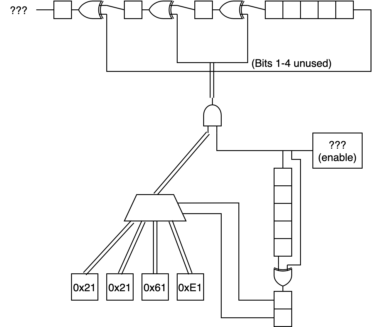
Here’s a diagram where I try to show an overview of everything so far and realize I’m bad at drawing diagrams:
Then I tried the same GF(2) approach, this time without off-by-one errors, with the lowest bit of the keystream bytes and it didn’t work. OK, what if we look at the 32 first bits of the enable bitstream (corresponding to the first 32 bytes of the keystream) for each firmware? This not too much to decrypt, and now that we know how the value bitstream is derived from the enable bitstream, we only have to know the enable bitstream to decrypt.
These are the bits:
| Revision | Bits |
|---|---|
| A0 | 00000011 00100100 10111101 00000100 |
| A4 | 00000011 00101000 11001000 11000110 |
| A5 | 00000011 00100111 11000000 10100000 |
| A6 | 00000011 00101010 11001010 10001000 |
| AA | 00000011 00101110 11001110 00001001 |
| AB | 00000011 00101101 11001100 10100101 |
One sees a first byte 0x03 in each of the streams.
Note that this is not the first byte of the keystream, but the first 8 bits of the enable bitstream, which is derived (or derives) the first 8 bytes of the keystream.
But the first byte of each firmware file is also 3, so maybe this bitstream is derived from the first few bytes of the firmware?
We would expect the following byte to somehow correspond to the revision number, since that is the second byte. It is not the same and it is not XORed with a constant value either.
On a somewhat long train ride, I decided to just stare at those bits, and I did have some success: It turns out that it is done using addition, but not of the revision directly.
| Revision | Bits 8-15 of Bitstream |
|---|---|
A0 |
24 |
A4 |
28 |
A5 |
27 |
A6 |
2A |
AA |
2E |
AB |
2D |
Yes, you guessed it, it’s as if bit 0 of the revision gets subtracted, but bits 1-7 get added (both to some existing value).
This can be equivalent to first XORing the value by 0x01 (maybe 0x81?) and then adding to it.
What we can take from this is that there is probably some addition involved instead of just XOR like one would expect with a traditional LFSR.
To get some clarity, it may be advantageous to take a look at some segments where the enable bitstream has long runs of 0s. Here, each line contains one of these runs (the bit before it is always 1, i.e. it starts at the beginning of the run of 0s):
00000000 <0000>1101 <0000>1011
00000000 <00>100111 <00>100011
00000000 <00>110101 <00>101110
00000000 <0>1100111 <0>1011000
00000000 <0>1000111 <0>0111100
See how the number of zeros at the start of the third byte is at least as big as that of the second one?
We can imagine a 16-bit state getting shifted and if the shifted out bit (which becomes the enable bitstream) is one, a value gets added to the state. Then this secondary run of 0s in the third byte would appear:
- the additions before the runs can at most change bottom of the second byte, since they reach 16 bits
- if the added value was an 8-bit value, the 1 at the end of the run only causes change 8 bits (7 with carry) later
This leaves a gap of unchanged bits, which stay at 0.
Similarly, take a look at some location pairs where only 1 bit in 16 bits is different:
10010100 0010011<0> 00001101 00100101
10010100 0010011<1> 00001111 00001110

10111100 1000010<0> 10110111 10011010
10111100 1000010<1> 10111000 01110011

10010000 1001011<0> 11110011 01011011
10010000 1001011<1> 11110100 10111010

00100111 0101001<0> 01010000 10110100
00100111 0101001<1> 01010001 10010100
The difference in the penultimate byte is mostly 1 (except in the first one with 2) caused by carry. This provides further evidence of an 8-bit value getting added 16-bits to the right.
So lets search the value that gets added, assuming it is a 8-bit constant that gets added to the 16-bit state if the enable bitstream is one. This shouldn’t be hard, since there are only 256 possible values.
Sadly no exact match is yielded, but one value is close: 0xDF: it doesn’t only match most of the keystream of A4, but also the beginnings of the others.
One might ask why the generated bitstream does not diverge from the real one at some point, but that’s because I was using the shifted out bits of the real one to generate the other one, instead of feeding to itself.
(Interestingly, this is almost a multiplication of the enable bitstream by 0xDF and shifting it 16 to the right to get the generated one, except for the few places where it overflows the 16-bit state).
The difference can be seen in this excerpt comparing the actual bitstream and the generated one:
Generated:     110000100111101000001100001001101
Original:      101111101001111010011000001101101
Difference:         -    +  +  +  + -     +
val bitstream: 000010011101101101101010011011001
It looks like one bit being off in the addition, sometimes +1, sometimes -1, which is shown in the third line.
For instance, the generated has 10000 and the original 01111, which is one less.
The positions of + and - are of course ambiguous, but one can try to minimize their number. I tried that for big parts of the A4 enable bitstream.
After a while I noticed something:
the + and - mostly appeared when there was the pair 10 in the value bitstream 8 to the left (I’ve conveniently already moved the value bitstream in the previous example 8 to the right to line it up).
Additionally, the bit before those two bits determines whether it is a + or -.
Some fiddling with the key derivation later, we have some code like this for the decryption:
uint8_t galConsts[4] = {0x61, 0x21, 0xE1, 0x21};
uint8_t iv[2];
fread(iv, 1, 2, f);
uint16_t state = iv[0] * 0x100 + iv[1];
// key derivation?
state ^= 0x81;
state += 1;
uint8_t galState = iv[1] ^ 0x7E;
uint8_t shiftReg = 0;
uint8_t buf[BLOCKSIZE];
int newbytes = fread(buf, 1, BLOCKSIZE, f);
while(newbytes > 0){
	for(int i = 0; i < newbytes; i++){
		bool currentBit = state & 0x8000;
		shiftReg <<= 1;
		state <<= 1;
		galState <<= 1;
		if(currentBit){
			shiftReg ^= 0x21;
			state += 0xDF;
			if((shiftReg>>5 & 3) == 2){
				if(shiftReg & 0x80){
					state += 0x100;
				} else {
					state -= 0x100;
				}
			}
			galState ^= galConsts[shiftReg>>5 & 3];
		}
		buf[i] ^= galState ^ 0x7E;
	}
	fwrite(buf, 1, newbytes, outfile);
	newbytes = fread(&buf, 1, BLOCKSIZE, f);
}
Surprisingly(?) it works on every firmware file available. But this is probably not how the original decryption algorithm is organized, since it seems very arbitrary and overcomplicated.
Dumping the Original Firmware
We have now not only revisions A4(b) available as plaintext, but every revision. AB contains the most code.
Now one thing useful to know about the ADNS-9800 is that DPI can be set separately for both axes with separate values or as one value, depending on whether bit 2 in the Configuration_II register is set.
Looking through the firmware, one finds some locations where it checks whether bit 2 in some byte is set and - depending on that bit - writes the same value twice to different SFRs or two different values to the two SFRs.
One interesting routine is where it writes 0 to some SFR if the configuration bit is not set, or some other byte if it is set.
This seems likely to be the function responsible for returning the Configuration_V register, which contains the Y-DPI iff the bit is set.
One can easily patch it to return another value than 0 and upload that (and ignore the failed checksum check).
Indeed, replacing that value with 0xFF seems to work, so let’s be bolder and try to read the code ROM.
We store a 16-bit counter in some location of the IRAM unlikely to be used and read from that address and increment it every time we read Configuration_V.
Luckily, there’s 23 bytes of unused padding in our firmware towards the end, more than enough for our purposes, so we insert our code there.
By reading the Configuration_V register 216 times, a firmware dump is obtained.
(And also do it a few more times, for good measure).
Now, we did not initialize the 16-bit counter to anything, so the firmware dump is shifted somewhat, but we know our segment of firmware is loaded at 0xc006, so we search for that and align it like that.
Looking through the dump, one finds the lower ~10kB to be filled with more 8051 firmware. The firmware upload function is quickly found: just go through the interrupts, find out that there are two big jump tables corresponding to the registers documented in the datasheet and find the one for writing firmware.
Finally, this is the original decryption algorithm in pseudo-code:
uint16_t state
for x in file_bytes:
    state ^= 0xC1
    state <<= 1
    if carry:
        state += 0xE1
That’s a lot simpler, isn’t it?
Tune in again next episode, where I’ll bit-bang 30x30 greyscale video at 230fps.