Reverse Engineering Firmware (in Mice)
Analyzing the USB Controller's Firmware
I was laying in bed with fever when my brain came up with the bright idea that I should write a driver for my recently acquired programmable
gaming
mouse.
The mouse itself was advertised as having a dpi of 16400 which is kind of a lie since the sensor just supports a max of 8200 and the movement offsets just get multiplied by two.
Being qualified as programmable
was not that true either - you could save key sequences to be executed when a button is pressed and set the RGB led color, but the software didn’t allow you to upload arbitrary programs.
Doing Protocol Analysis
When trying to find out how a program communicates with a device, it is most often easier to look at the data transferred than reverse engineering the application itself.
It was time for the Windows-VM to start up, since the program to change the mouse’s settings only came for that OS. Running on the Linux host was Wireshark which captured the USB traffic coming from the VM.
I tried out pretty much all the application’s features and labeled them in Wireshark. After that, I rested because my fever was at 40°C and my headache became too uncomfortable.
When the illness finally subsided, I started doing protocol analysis on the captured packets. How does this work? In this case it was fairly simple: you execute similar actions and look at what changes and what doesn’t change. You then start doing more different actions until you manage to change most fields.
Some notes on USB before this: USB has various transfer types like interrupt transfers (the mouse uses this for sending the movement data) and control transfers (for getting information and changing settings on the device).
In this case, control transfers are used by the application to send SET_REPORT and receive GET_REPORT packets, both specified in the USB HID standard.
The values in the standard-defined fields are mostly uninteresting, interesting is the fact that the application sends some vendor-specific data in SET_REPORT and also gets some from the mouse with GET_REPORT.


One simple setting the mouse has is the profile, which can be set from 1 to 5.
Each profile contains some presets on RGB led color, dpi etc.
The profile number is set with a SET_REPORT request containing 16 bytes of data.
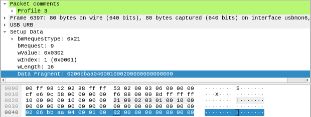
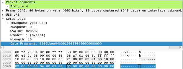
Let’s look at two packets, the first one setting the profile to 3, the second one to 4.
In the marked segment of the hexdump the only different byte is at offset 8. When choosing profile 3 it has value 2, on profile 4 it is 3, so the profile most likely gets transmitted as an index starting from 0.
With some further analysis, the meaning of some more fields is revealed: we already know from the USB HID spec that the byte at offset 0 has the value of the Report ID. In the case of this mouse this seems to indicate the size of the data, where the packet has the size 4n if n is the Report ID (even though the data length is transmitted in a separate field anyway). For some reason, the data always seems to always have a length that is a power of 4.
The byte at offset 1 decides what kind of data follows - the 6 in this case specifies a format to change individual settings. Right now, the specific format of the rest of mode 6 is not really important, so let’s take a look at what happens when a macro is written.
How Macros are Saved
The mouse allows executing a sequence of key presses to be executed on a click. Because it does not need any drivers and the macro persists across reboots and different hosts, the sequence has to be saved on the mouse.
When writing three macros one after another, following packets data gets transmitted:
| First Macro | Second Macro | Third Macro |
|---|---|---|
SET_REPORT: 0205 bbaa 000c c800 8x00 |
SET_REPORT: 0205 bbaa c80c c800 8x00 |
SET_REPORT: 0205 bbaa 900d c800 8x00 |
GET_REPORT: 0403 000c c800 fafa 248x00 |
GET_REPORT: 0403 c80c c800 fafa 248x00 |
GET_REPORT: 0403 900d c800 fafa 248x00 |
SET_REPORT: 0404 bbaa 000c c800 248 bytes |
SET_REPORT: 0404 bbaa c80c c800 248 bytes |
SET_REPORT: 0404 bbaa 900d c800 248 bytes |
SET_REPORT: 0206 bbaa 4000 0800 0400 0001 0001 0000 |
SET_REPORT: 0206 bbaa 4000 0800 0400 01bd 0001 0000 |
SET_REPORT: 0206 bbaa 4000 0800 0400 02c9 0001 0000 |
Ignore the last packet in each column for now, it just informs the mouse which button to use for the macro.
One place that changes in the first three packets (apart from the last 248 bytes of the third packet) are two bytes common to all three of them:
000cc80c900d
Another eye-catching similarity is the c800 that always follows right behind it.
If one looks closely enough, one eventually figures out that they are intels (INTeger Endian Little, I can remember it easier that way since it’s the endian used in x86, note also the inverted order of the words themselves) and that 0x0c00 + 0x00c8 = 0x0cc8 and 0x0cc8 + 0x00c8 = 0x0d90.
What does this mean? We can infer from this that it is probably an address + length pair.
Since the third packet is the only large packet going to the mouse, it has to carry the data of the macro, so the content has to be written to the mouse.
The second packet seems to have the same size as the third packet. It travels from the mouse to the host and contains only zeros in the last portion, so it is probably a read from the unwritten memory before the macro was written.
The first packet then has to contain the address + length to read, as that can’t be transmitted in the GET_REPORT packet itself (it probably can by stuffing it somewhere in the header, but it’s unlikely).
One also conjectures that the byte at offset 1 (05, 03, 04) determines if it is an address-set/read/write.
A question that immediately springs to mind is Can this be used to read data other than macros on the mouse?
Firmware Analysis
Dumping the Firmware
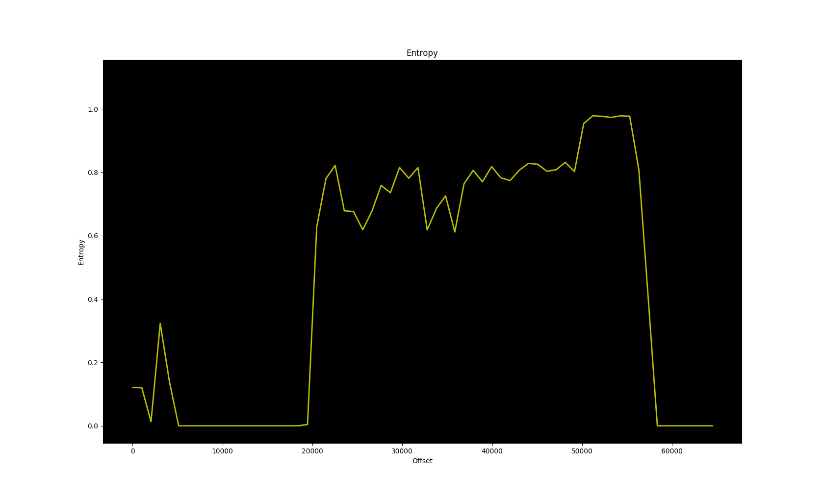
Using the hidapi library, I first tried to read the addresses the macros were written to, and it indeed returned the content of the macros that were previously written. But the address is a 16-bit integer, so it is possible to read every address and dump it. Let’s take a look at the entropy of that dump:

It looks like it doesn’t repeat and the entropy is reasonably code-like. That means we probably dumped the code ROM, which is nice. Let’s take a look at the distribution of the bytes, more specifically the ten most abundant bytes:
    701 04
    747 90
    776 06
    798 e0
    799 02
    817 e4
    842 e5
   1129 f0
   1440 f5
  28341 00
Aside from all the zeros from the unused areas, this sure looks like 8051 opcodes, an 8-bit architecture pretty often used in usb controllers:
As an example, f5 is the opcode for mov direct, a, which is regularly used for writing to SFRs (special function registers, similar to I/O ports).
All the others are also common in 8051 code.
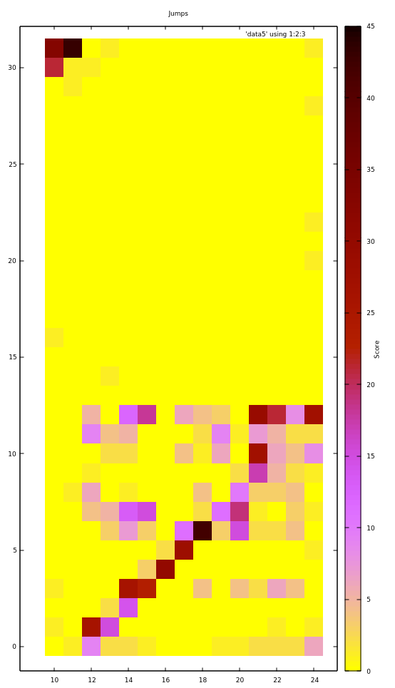
There’s one problem when trying to disassemble it: the absolute jumps and calls don’t seem to lead to reasonable locations, so our image is probably not loaded at the right location. To visualize where it probably is loaded, let’s plot the origin of the jump vs. the target, since they should still be somewhat close (because of the way programs are usually linked).
The plot is grouped into 2048 byte blocks and only addresses which are probably code are considered; x-axis is origin block of jump, y-axis is target block.

First off, the diagram starts at block 10 (address 0x5000) because there is no meaningful code before it, and the entire address space - 32 blocks - is considered in the y-axis as the jump target.
In blocks 10 and 11, jumps go almost exclusively to blocks 31 and 32.
Similarly, from block 12 to 24 the jumps go mostly to blocks 0 to 12. Furthermore they do that pretty linearly - if the current block is 12+x, the jumps go mostly to x.
This suggests that blocks 10 and 11 are actually towards the end of the address space and it wraps around at block 12, which is at the beginning of the address space. We could try to rotate the image so that address 0x6000 is now at address 0. It turns out that this happens to be the right address and we are lucky and don’t have to look at the offset within a block.
Another question is whether we can also write to arbitrary locations. Alas, the firmware seems to limit the write so that writes to code areas are not possible, more on that later.
Analyzing the Firmware
I did take a brief look into the mouse hardware itself, but there seems to be no datasheet anywhere for the controller itself, so we have no information on the SFRs; while there are some standard SFRs for 8051s, many are hardware-specific and generally unknown unless you have a datasheet. There was also a JTAG port, but I want to see how far I can take this without touching the hardware itself (well I do touch the mouse when I move it, but you know what I mean).
Now before I start this, some information about the workings of the 8051 is in order. The 8051 has 3 address spaces, code ROM (16-bit), external ram (16-bit) and internal ram (8-bit).
- The internal ram with 256 bytes is the fastest and best supported by instructions.
- The upper half of the internal ram consists of SFRs, which means there is a total of 128 SFRs.
- The Code memory is where code is stored and executed. It can normally only be read from in a standard 8051, however there are many ways a custom 8051 core allows writes to it.
- The external memory is used as a slower version of the ram which is more inconvenient to access. As it is 16-bit, it can have up to 64k bytes. It is sometimes also used for additional I/O.
When analyzing 8051 firmware, one just disassembles around with no goal in particular, looking for stuff that seems familiar.
For one example, some explanation on the color configuration of the mouse is necessary. Each profile has 5 dpi presets you can choose. You can also set the color for each preset, but that color only applies to the main LEDs.
There’s another LED for the scroll-wheel where the color is not configurable and also varies per DPI preset. It goes like this for the 5 presets: yellow -> green -> blue -> magenta -> red, all color attainable with 3-bit RGB.
Now going through the code (translated to pseudo-C) one finds this:
void fn_60d(void) {
    switch (*0x68) {
        case 0:
            P5.0 = 0;
            P5.1 = 0;
            P5.2 = 1;
            break;
        case 1:
            P5.0 = 1;
            P5.1 = 0;
            P5.2 = 1;
            break;
        case 2:
            P5.0 = 1;
            P5.1 = 1;
            P5.2 = 0;
            break;
        case 3:
            P5.0 = 0;
            P5.1 = 1;
            P5.2 = 0;
            break;
        case 4:
            P5.0 = 0;
            P5.1 = 1;
            P5.2 = 1;
            break;
    }
    return;
}
(P5 is a whole byte of a port and P5.0 means the 0th bit of the port P5).
One immediately (not meaning very soon, but as a sudden realization) notices that the set bits are just the bitwise inverse of the corresponding DPI colors for the scroll-wheel. For example, with the first DPI preset, the color is yellow, which is 110 in 3-bit RGB and the case 0 above sets the three ports to 001, the inverse of 110.
So we now know that the caller of this function probably updates the DPI. Indeed, looking at what the caller does prior to this, it reads the DPI value for the preset from memory and bit-bangs it over SPI. We now know which ports to use to communicate to the sensor and where the DPI preset is stored internally.
In a similar way we find out how the mouse communicates over USB. This kind of I/O is often done inside interrupts, so one looks at the interrupt vector, which in the 8051 are at addresses 3 + 8n, n ∈ ℕ₀ (= ℕ).
In one of them, there is a routine that compares two bytes to values in a table and jumps to an address depending on which entry in the table matches those bytes. This is that table
| Bytes | Address |
|---|---|
00 01 |
6461 |
02 01 |
5d29 |
00 03 |
6451 |
00 03 |
6451 |
00 01 |
6461 |
02 01 |
5d29 |
00 03 |
6451 |
02 03 |
603f |
00 05 |
6307 |
00 09 |
6003 |
01 0b |
5be5 |
00 07 |
0046 |
80 00 |
5b8b |
80 06 |
3009 |
81 06 |
3009 |
80 08 |
6183 |
81 00 |
5c8d |
82 00 |
50cd |
81 0a |
624e |
a1 01 |
274c |
21 09 |
15a3 |
21 0a |
6362 |
a1 02 |
629c |
21 0b |
61ad |
a1 03 |
6079 |
Especially towards the end, those bytes seemed familiar to me.
Indeed they are familiar, I know them from the USB HID specification and Wireshark, they are the bmRequestType and bRequest fields of the USB control packets.
Particularly, SET_REPORT has 21 09.
Let’s have a look at the function at address 0x15a3.
Since the protocol was analyzed earlier, one can then go through what happens if a certain packet with known functionality is received. For example, one could try to find out what’s preventing us from writing to code areas.
First Try Writing to the ROM
What happens when we try to write out of bounds?
First, if the data arrives in a packet bigger than 16 bytes (so Report ID > 2), it gets sliced up into at most 200 byte segments and each one gets written into a buffer inside of XRAM. For each segment, a write function is called with the buffer address, destination address and length.
The write function first checks if the destination address is < 0x2FF0 and returns if it isn’t.
After that it adds an offset of 0xA000 to the destination address, which is why the firmware image wasn’t aligned, since the read function does this too.
It then writes the buffer to the ROM.
While the write function doesn’t take the length into account, with above conditions it is only possible to write 200 bytes over the bound of 0xA000 + 0x2FF0 = 0xCFF0, which still isn’t enough to reach the code starting at 0xEFFC.
However, that is only the case with packets whose Report ID is bigger than 2. With Report ID 2, the eight last bytes of the packet are put into a buffer of 8 bytes inside of IRAM. The write function is then called, with the IRAM buffer, the given destination address and the given length.
But we control the length and don’t have a 200 size per write anymore.
Therefore we should be able to write over the boundary without limit.
The buffer is assumed to contain no more than length bytes by the write function, so it will just continue past the buffer.
IRAM is only 256 bytes before it wraps around, so the writing function will repeatedly write the 256 bytes of the IRAM, 8 bytes of which we control.
An excellent target for modification is a jump sitting in address 0xEFFC-0xEFFE, with no important data before it.
By setting a length of 256x + 3, we are able to control the last 3 bytes of the write.
With x = 33, the destination address would be 0x2EFC (0xCEFC if 0xA000 is added) and the length would be 0x2100.

Unfortunately, this doesn’t seem to work.
The flash page at 0xE400 seems to be unwritable or at least writing to it causes the watchdog in the mouse to time out.
We need another approach; an approach more trivial than any other.
Invoking Recovery Mode
Do you remember that Block of Code towards the end of the firmware mentioned when aligning the firmware to its rightful address? Well, such code is normally boot code, and indeed the first jump in the firmware points straight to it.
What does boot code do? Sometimes it does some hardware initialization, but sometimes it also loads firmware. And that’s exactly what our boot block does.
First off, one finds a table quite similar to the table of two bytes and jump targets found in the USB handling interrupt.
And once again, the SET_REPORT and GET_REPORT functions are the ones we are interested in.
When looking at the function belonging to the SET_REPORT of the boot block, one sees some SFR write sequences already used in the write functions, in particular this one:
MOV 0xF2, #0x6E
MOV 0xF3, #0x05
MOV 0xF4, #0x0A
MOV 0xF5, #0x09
MOV 0xF6, #0x06
This sequence only occurs in the boot block and the write function, where near SFRs also contain the address and the byte to be written. Therefore, we can be pretty sure this is used to write the bytes to the ROM.
Another sequence is the one to clear a flash page.
Looking through the boot block, one finds out how to clear the firmware, write new firmware on it, do a checksum and finally do a jump to restart it.
Now we just have to invoke it somehow.
By searching for the addresses where the functions start, we trace it backwards and eventually arrive at the SET_REPORT function of the main firmware block.
Looking at which branches we take, we can then figure out the packet contents to invoke the recovery mode: 0203 aabb 0100 0000 0000...
We can now write arbitrary firmware, but there’s something yet unknown in the firmware image: a blob of high entropy. Because this post has become long, see the next post.