A tour of my laptop's firmware
Realtek WiFi Firmware and a Fully 8051-based Keylogger Using RealWOW Technology
In the previous blog post, I looked at the EC firmware in my laptop. This time I will look into the WiFi firmware of the same laptop.
The Realtek rtl8821ae Chip
The wifi chip is located on a m.2 module that can be swapped out in my laptop. It has features like 2.4GHz and 5GHz wifi support and stuff. Communication with the wifi chip happens over PCIe.
Finding the firmware is easy: it is loaded at startup from /lib/firmware/rtlwifi on startup on Linux.
There are actually two sets of firmware: one for normal usage (rtl8821aefw_29.bin) and one slightly smaller for Wake on Wlan (rtl8821aefw_wowlan.bin), a technology for waking devices over wifi.
The ..._29.bin gets loaded on ip link set dev wlan0 up, the ..._wowlan.bin gets loaded on ip link set dev wlan0 down.
They are not permanent firmwares but merely loaded into the RAM of the chip.
The chip also has an upstreamed wifi driver in the Linux kernel written by realtek. That does not say much about its quality, as it is still a driver written by realtek.
On the same chip there is also a Bluetooth chip which can be spoken to over USB 2.0. There appears to be some BT-Coexistence protocol implemented in the kernel to make sure the wifi and BT part do not interfere.
All communication with the rtl8821ae is memory mapped: there is a 4K sized configuration space which can be written and read from. Furthermore, there are a 64K tx buffer and a 64K rx buffer for sending and receiving packets.
The Basic Firmware Structure
Looking at the firmware, it is clearly 8051-based (of course it is).
However it is not loaded at 0x0000.
at51 base returns 0x3fe0 when ran directly on the firmware image.
It turns out there is a 0x20 byte header, so the firmware itself is loaded at 0x4000.
The code path starting from 0x4000 also leads to the main function:
in typical Keil compiler fashion, it jumps to the ?C_START function, which is a function for initializing static variables emitted by the Keil C(X)51 compiler that initializes static variables.
After that it jumps to the MAIN function.
The MAIN function is a bit strange: it sets up some memory, then pushes an address to the stack, sets up a timer and returns to the address it just pushed onto the stack.
It turns out that realtek is using the RTX51 tiny, which is a very small real-time kernel that manages tasks and signals.
The kernel basically keeps track of the task states and relocates the stacks of tasks when switching them.
at51 libfind finds out the location of various Keil libraries, and as part of those it also finds rtx51 kernel functions like OS_SWITH_TASK or _ISR_SEND_SIGNAL.
There are two tasks (and one additional that is used only for initialization) on the normal firmware: one is only activated for specific signals, and the other one runs in an endless loop.
While there is no public datasheet documenting the I/O registers from the 8051 side, most of it is refreshingly easy to find out:
the Linux driver defines the registers in the configuration space from the host side.
By looking at what registers the 8051 does not access, one sees that those are similar to those not defined in the driver source when mapped to XDATA offset 0x0.
It is then easy to simply do some processing on the reg.h file defining the registers to import all of the names into ghidra.
Dumping the Mask ROM
The firmware is loaded at 0x4000, but it still does calls to functions below 0x4000, which means that there is a permanent mask ROM on the chip that is also responsible for downloading firmware onto the chip.
Not knowing these functions makes reverse engineering a bit hard, so it would be nice to obtain that firmware.
The easiest way to do that would be to modify the firmware and copy the bytes from CODE space into a configuration space register, since we already know how those are mapped.
But there is a hurdle: the last two bytes of the firmware appear to be a checksum, which means we need to know how the checksum is calculated.
However the checksum would be calculated inside the mask rom, so we can not just look at the firmware to look how it is done.
Luckily, delsum quickly tells that it is simply a 16-bit XOR checksum (which is equivalent to a CRC with poly=0x0001).
Reading and writing the configuration space is usually not possible from user space, so I needed to recompile the kernel to add support for doing that with /dev/mem.
I chose to do this by executing the kernel inside a VM and mapping the wifi card into it using VFIO since recompiling distributors kernel takes too long for me and the standard configuration pretty much only works on VMs.
(Yes I know modconfig is a thing, but the VM approach still works fine with a standard config and does not take that much more time).
The kernel communicates with the firmware on the chip mostly using something called H2C which basically puts some short (something like 8 bytes) commands into config space and lets the firmware read that.
It is easy to find the firmware code that reads the spot by looking at the references from the firmware to that spot in ghidra.
Unfortunately, I could not get the firmware to respond when doing those transactions myself.
Deciding not to waste too much time on that, I then simply decided to hard code the address that is read into the firmware.
The jump at 0x4000 is modified to copy the byte from the hard-coded address to an unused configuration space register (REG_ROM_VERSION) and the execution then continues to main.
For each read address, the firmware is modified and the kernel module is reloaded with the firmware modified with a new address.
The read speed with that approach is roughly 3 bytes per second.
This took a couple hours and was probably still faster than figuring out why the firmware did not respond to H2C commands (and I could do other things in the meanwhile anyway).
The Bluetooth Firmware
One thing I did not realize at first but which seems obvious in retrospect is that there is also a separate Bluetooth firmware for the chip (in /lib/firmware/rtlbt).
This time it is not 8051 based, but I could not easily find out what the architecture is.
To help in figuring this out, I made a tool (I link my own tools way too much for my own liking, but the thing is that I make them precisely because I repeatedly need their functionality) which compares different revisions of firmware by comparing them using pairwise alignment so that sections that are the same but at different addresses between different firmware revisions still get shown side by side.
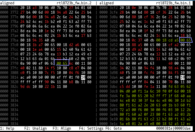
What is important to see is that in many places, the bytes 00 65 are inserted and after that, both addresses are aligned by 4 bytes, which means it is used as a sort of padding.
Of course, the perfect instruction to use for padding would be NOP.
So I searched, but “0065 NOP” did not really result in anything, but searching for “6500 NOP” (opposite endian) did result in a few interesting results that indicated that mips16e (a thumb extension for mips) uses that opcode for NOP.
And indeed, that did the job of properly disassembling the firmware to something that makes sense.
However I was not that interested in the Bluetooth firmware itself (and it is not 8051 based) so I went on with my analysis of the wifi firmware. In the first place, I do not really own any Bluetooth devices (except maybe my 8 year old mobile phone that runs on android 4.4) so testing stuff with it would be hard.
How the Driver Sends Packets
The way wifi works is specified in the 802.11 specification. When opening it, one is met with 3500 pages of dense abbreviation-packed words. However I kind of like reading specifications and standards, so that is not a huge issue (at least to me).
802.11 frames have kind of the role of ethernet frames, but instead of carrying just data there is also a wide variety of control frames to do certain stuff like association with an AP, authentication with an AP, power management etc. Data frames (and some control frames) can also be encrypted with a variety of ciphers and protocols.
In the case of encrypted frames, there is also some additional data like a sequence number whose purpose is replay protection, and this also means that 802.11 data frames can have different sizes depending on whether they are encrypted.
The encryption is usually done by the rtl8821ae itself, the driver just puts the unencrypted content into the frame where the encrypted would normally reside and the chip encrypts it using hardware.
Inside 802.11 data frames there is then a LLC header which in most cases is only for telling the EtherType of the content.
When sending a packet, the driver puts the whole frame into the tx buffer, with a 40 byte header in front of it. The header tells the wifi hardware the size of the frame, whether to use encryption, the rate at which to send and similar things. There is also a duration field inside the 802.11 frame which indicates how long the packet takes to send and that is also calculated by the hardware.
The hardware has 8 queues for varying purposes that can be specified in the header, one for beacon frames, one MGQ (management queue?) and a bunch for just sending normal stuff. Regardless of queue, the packets are put into the tx buffer in round-robin fashion on 256-byte boundaries.
Welcome to use Realtek RealWoW Tech
In the Linux driver, there is a function called rtl8821ae_set_fw_rsvdpagepkt that gets called when new firmware gets loaded.
It loads frames like a beacon frame and a data frame containing an ARP response into the higher end of the tx buffer, which is considered a reserved area by the driver.
The offset of these frames is then sent to the firmware via some H2C commands.
This is apparently also for wowlan purposes, so that the firmware can respond to ARP requests while the host is sleeping so that packets can be sent via IP to the wifi chip. One other thing the wowlan firmware is responsible for is the GTK handshake, where the AP sends a new group encryption key for broadcast/multicast purposes to all devices when a device leaves or joins the net.
To find out how the firmware deals with these, one looks at the H2C command that saves these offsets. It writes them into some XDATA locations, so by looking at what references these location, it can be figured out what part of the firmware sends the frames.
It turns out that there is a 256 byte window into the tx buffer in XDATA 0xfc00-0xfcff and the higher 8 bits of the address can be set with the XDATA register at 0xfd10.
Similarly, the rx buffer can be accessed from XDATA 0xfb00-0xfbff with the higher 8-bits at 0xfd11.
When sending the packet, it is kind of hard to figure out what in particular sends the packet because there is a lot going on.
The firmware sets some fields in the tx header, also sets some bits in the 802.11 header, figures whether it is encrypted to figure out the offset of the content, for ARP packets it also checks things like the EtherType and sets the destination address from the response (and of course even higher complexity is present when parsing the packets).
The essential part to sending a packet seems to be done by setting REG_TXPKTBUF_MGQ_BDNY to the higher 8-bit of the txbuffer address (note that the packets are 256-byte aligned) and then writing 0x20 to REG_CPU_MGQ_INFORMATION + 3.
Looking at the wowlan firmware, one finds that there is one further H2C command which seems to set even more configuration for additional packets.
In the parsing code, there is also a place where it checks for byte 0x45 at a beginning of the frame data content, which is how an IPv4 packet starts.
The parsing code then checks for a destination address and UDP port given by the aforementioned H2C command and checks the data against a pattern that is supposed to be placed into the tx buffer.
If everything matches it then puts the byte 0x30 as the wowlan wakeup reason and wakes the host.
In the Linux driver source, that reason is named FW_WOW_V2_REALWOW_V2_WAKEUPPKT (and is not really handled).
So what is this so called RealWoW?
The RealWoW website should answer all questions.

Unfortunately the Linux driver does not implement the Realtek RealWoW Tech (and it is not clear how one would obtain a new ID from realtek) so I did not have the joy of trying it out.
But analysis of the firmware reveals that it probably works by regularly sending a UDP packet (given by the driver) to the server, which responds with some kind of ACK. When the right ID is typed into the website, the server then sends a wakeup UDP packet to the device (which it can do because a connection is already open because of the regularly sent UDP packets). The wifi firmware then wakes up the device through PCIe.
A Purely 8051-based Keylogger
Now that the firmware is somewhat figured out, how about making our own changes. In the previous post, I analyzed the EC firmware. So how about making the 8051s talk to each other? 8051s love talking to each other after all, otherwise USB would not exist.
The plan is to make the EC take the keystrokes of the laptop keyboard and send them to the wifi chip, which sends them to the net.
DMA will not work from the EC: it is behind an LPC bus which means it would rely on ISA DMA which is horribly bad and also can only access the lowest 16MB of memory. Therefore, communicating via DMA is out.
Let’s take a look at the diagram from the previous post:
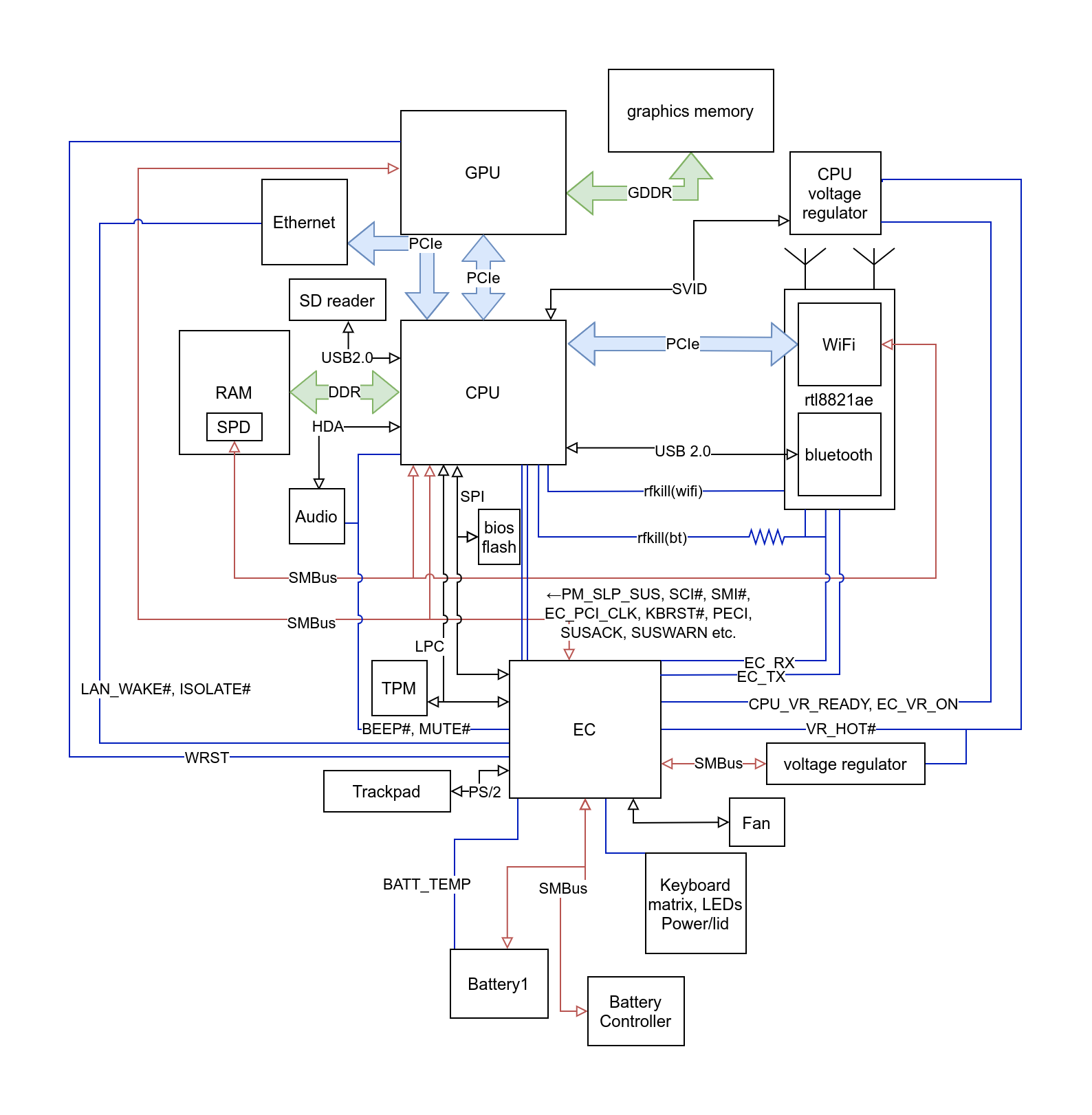
Now I wrote that the EC_TX and EC_RX traces (lower right between EC and rtl8821ae) are not connected on the wifi m.2 chip.
But notice that the EC_RX trace is also connected to the rfkill(bt) line via another pin (and there is a resistor on the way to the CPU so that the EC can effectively override the CPU without causing a short).
How about using that for transmission of data?
After some testing, it does seem like the line actually kills the rf ability of the wifi too. But that turns out to be not that big of an issue if one just pulls it low again after using it since both the host and firmware only seem to see that some packets are dropped.
Because there is only one trace, the controllers have to be synchronized in some way that is not a separate clock line. I decided to go with an UART-ish approach, meaning that bits are just transmitted one after another with a set time interval between them.
The EC already uses an 1ms timer, so I just patched the timer interrupt to check for new keys in the 16-byte keybuffer and send them over the EC_RX pin at 1 bit/ms.
On the wifi side, there was a problem with executing firmware. It turns out that the wifi firmware just stops executing after a short time to save power. Instead of trying to read the realtek driver to figure out how the power management works, what also seems to work is regularly doing writes to the configuration space which seems to keep it awake.
Now the wifi firmware also needs to know some concept of time. There are standard 8051 peripherals in it, however they do not seem to generate interrupts, so they have to be polled in a main loop. A quick experiment reveals that it ticks at roughly 6.67 MHz, which would mean that the 8051 uses a 80MHz clock source and that seems to be backed up by some mentions of 80MHz in the driver source.
Another experiment reveals that changing the rfkill(bt) line changes bit 3 of REG_GPIO_PIN_CTRL_2, so with that done it is now possible to implement the other side of the UART.
I simply set the timer to generate an overflow every 1/3 ms so that there is a higher sampling rate for the UART to work properly.
Once a byte has been transmitted, the EC pauses some time before the next byte.
While the EC is waiting the wifi chip sends a UDP packet containing the one byte to the configured IP address and port. It does so over unencrypted wifi.
While encryption is probably possible, it also is slightly more effort: the sequence number has to be updated and if the host is also transmitting packets, one would have to go through the tx buffer to find out the current one. It would also fail to send some packets from the host because of duplicated sequence numbers. It would probably also be possible for the firmware to scan for unencrypted wifi networks that are around, associate with them and then send the data over DNS, which typically bypasses potential captive portals.
On a raspberry pi I then setup a small program that accepts the UDP packets and converts the PS/2 codes to uinput events. That way, the keyboard effectively acts as the keyboard of the raspberry pi too.
The funny thing is that this is effectively a keylogger that does not run any code on the CPU while it is running. One only needs to flash the firmware of the EC once and needs to replace the wifi firmware so that the modified version is loaded.